# Replacement of Plate & Sponge Attachment
Replacement plates and sponges can be purchased from the official shop (opens new window) or requested for replacement from Diver-X.
DANGER
The replacement process takes approximately 15 minutes per hand. Please perform the replacement when you have enough time and avoid leaving the device disassembled.
If any damage occurs during the replacement, repairs or replacements for that specific area are not covered by the warranty. Therefore, carefully read the instructions before proceeding and exercise caution.
During the replacement, please adhere to the following:
- Do not disassemble the device in a way other than the specified steps.
- Do not use tools other than manual screwdrivers.
- Avoid using sticker removal liquid or blades when peeling off stickers.
- Perform the operation for one hand at a time. The bending sensor has left and right distinctions to avoid mixing them up during the process.
The following steps are for the left hand. When replacing the right hand, mentally mirror the images.
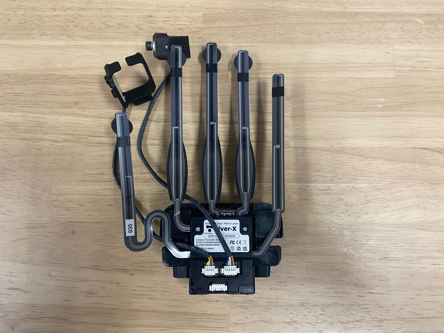
1. Initial Position
Start with the device removed from the glove. Refer to Separation Method (opens new window) for how to remove the device from the glove.
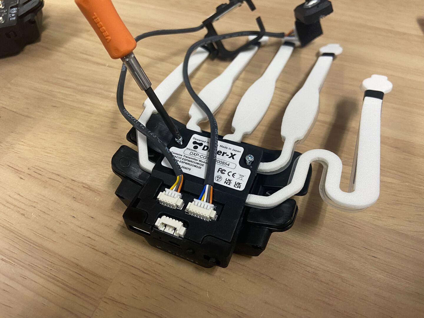
2. Removal of Back Cover Screws
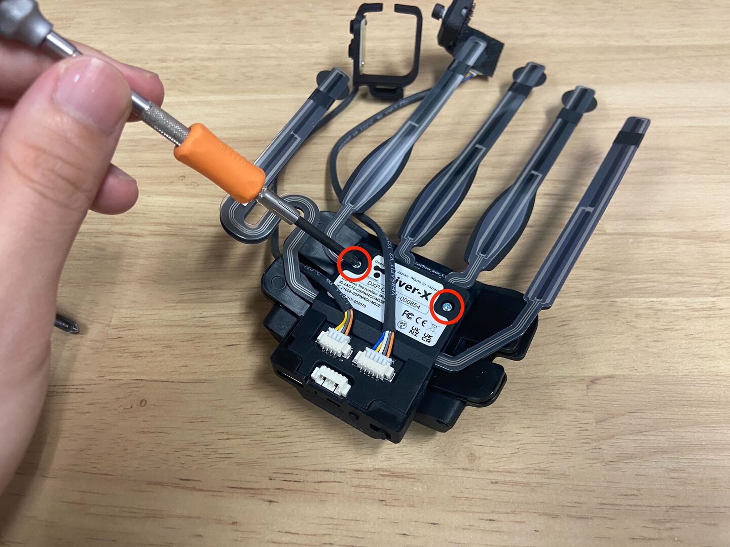
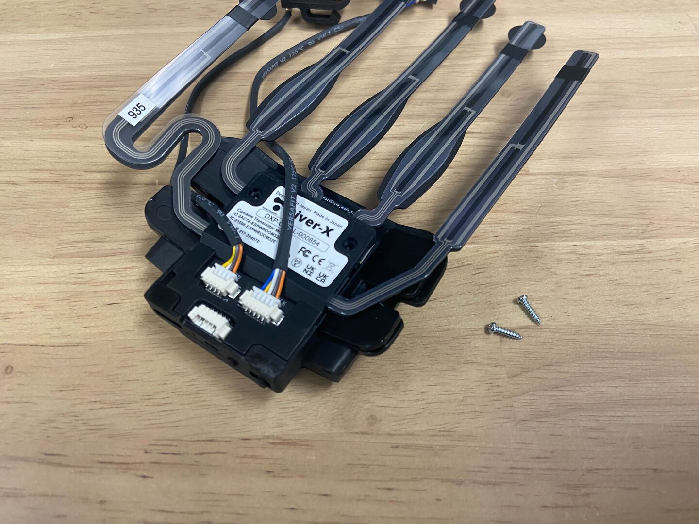
Store the removed screws to avoid losing them.
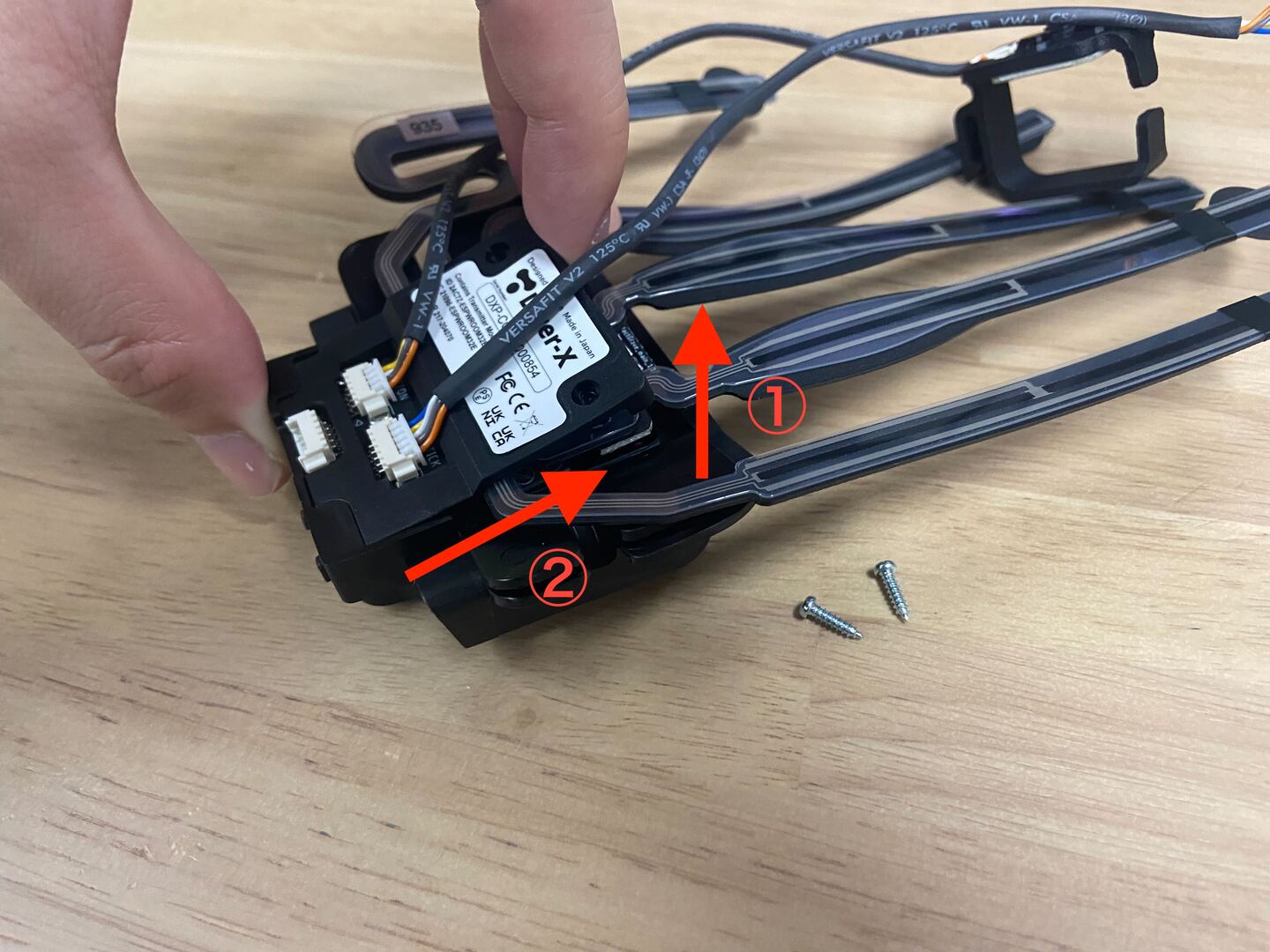
3. Removal of Back Cover
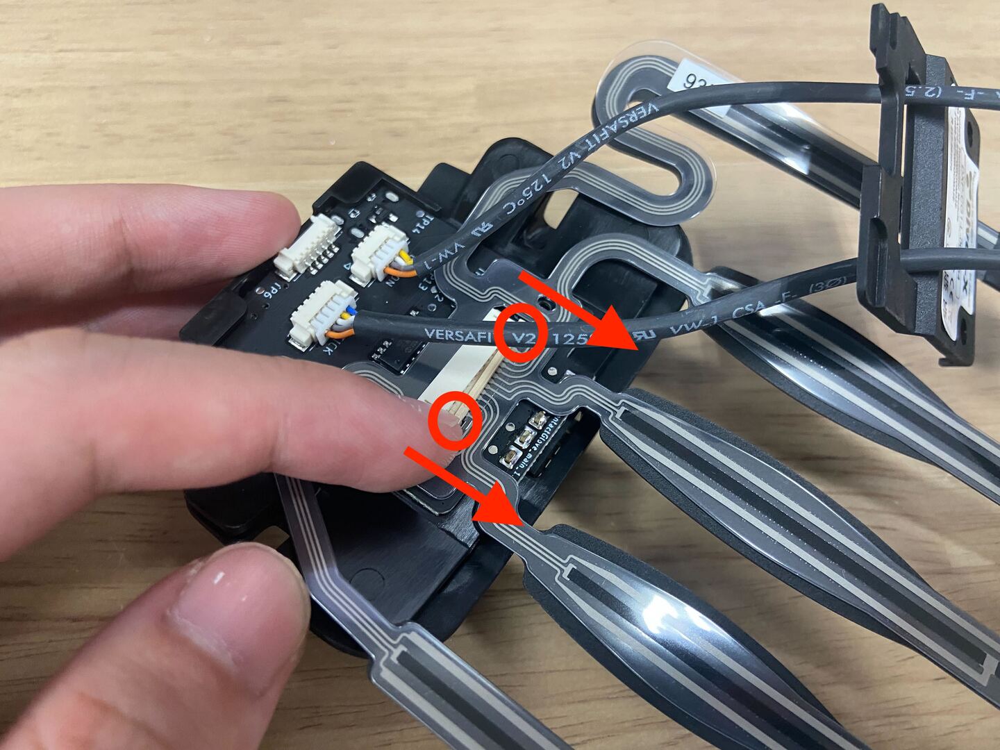
After lifting in the direction of ①, pull in the direction of ②.
When removing the back cover, there is no need to unplug the joystick or button cables. (Do not unplug them.)
Move the removed back cover outside by passing the cables through the holes.
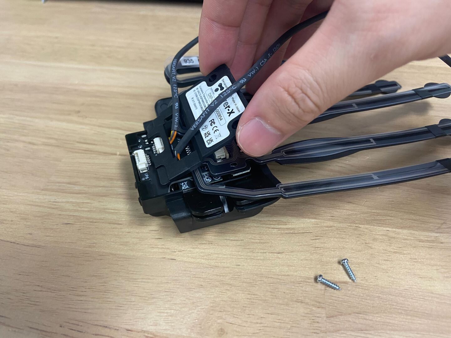
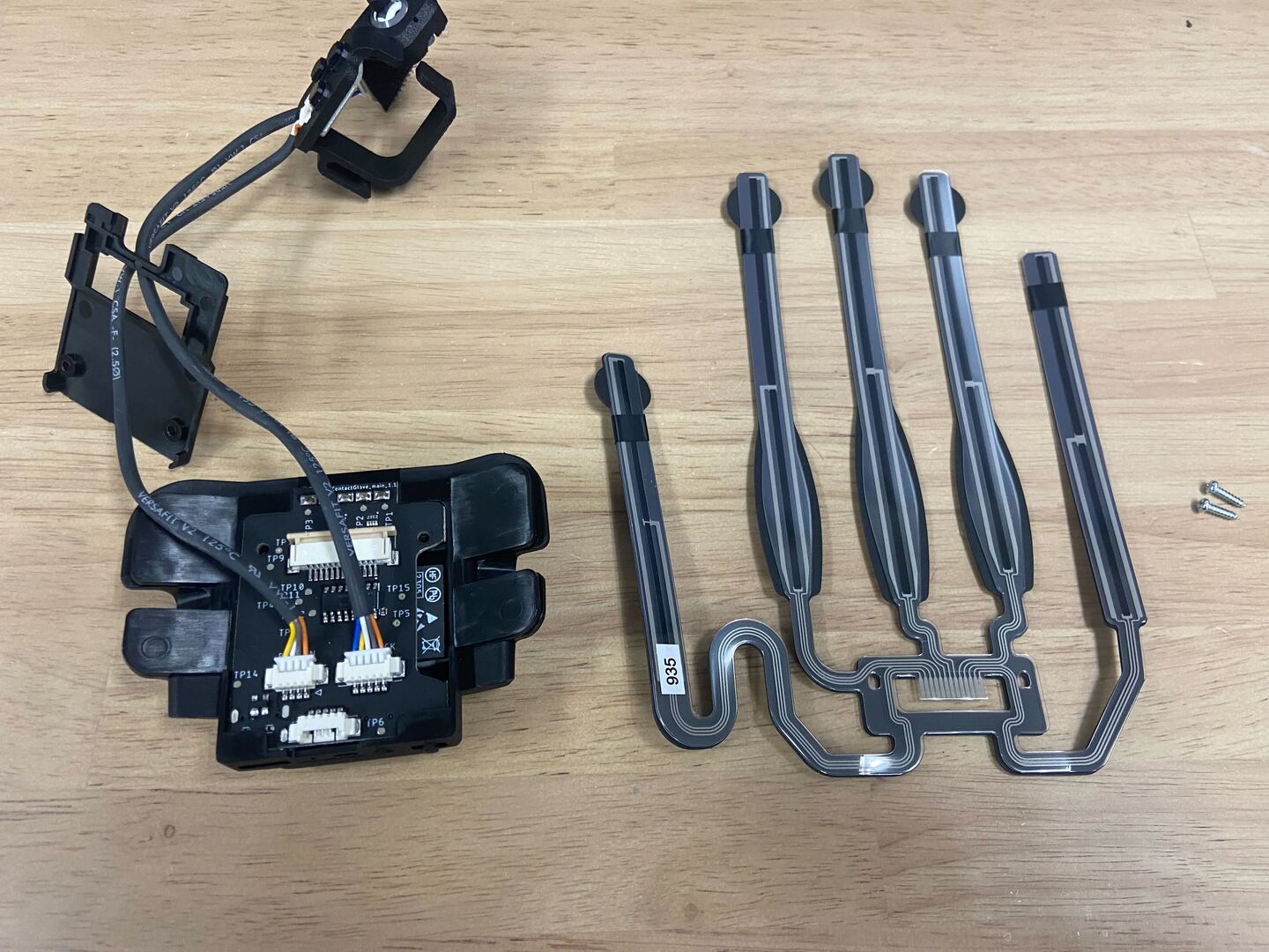
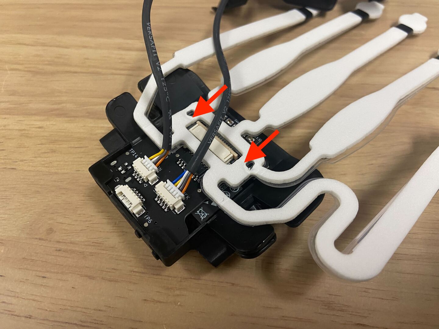
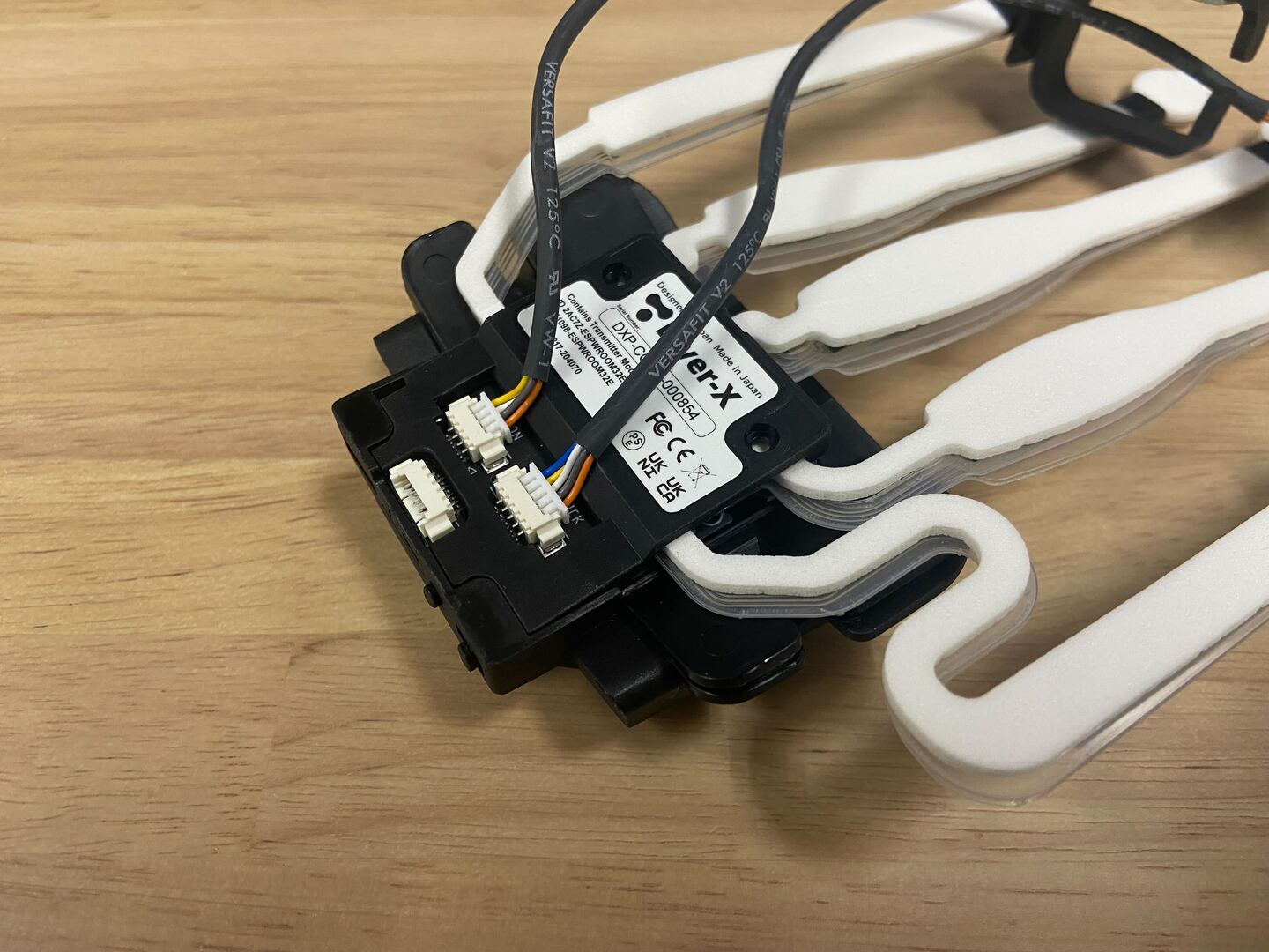
4. Removal of Bending Sensor
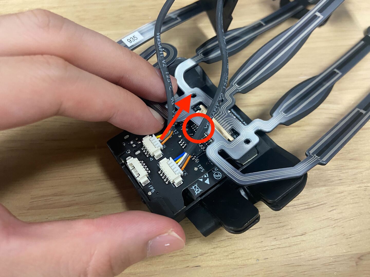
Unlock the thin yellow flap of the FPC connector.
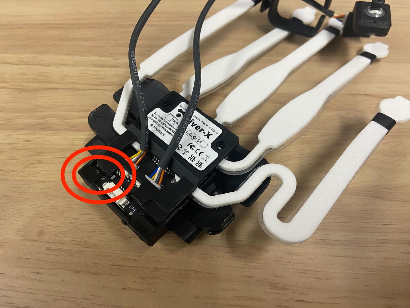
Lift the tail of the bending sensor (red-circled part), and the bending sensor will naturally detach.
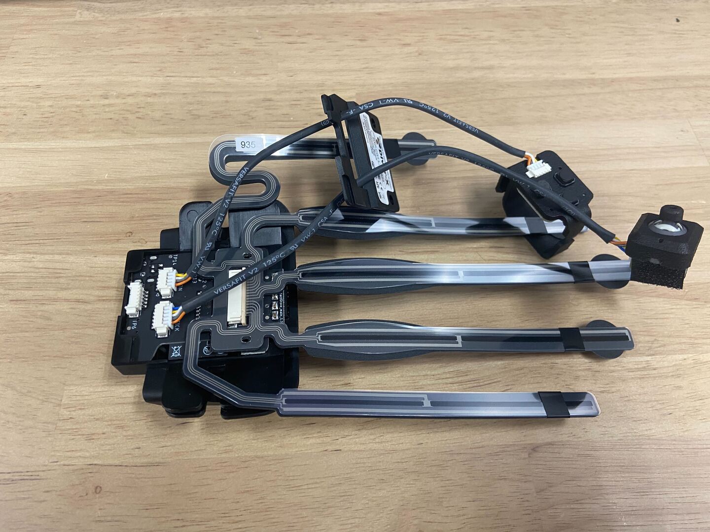
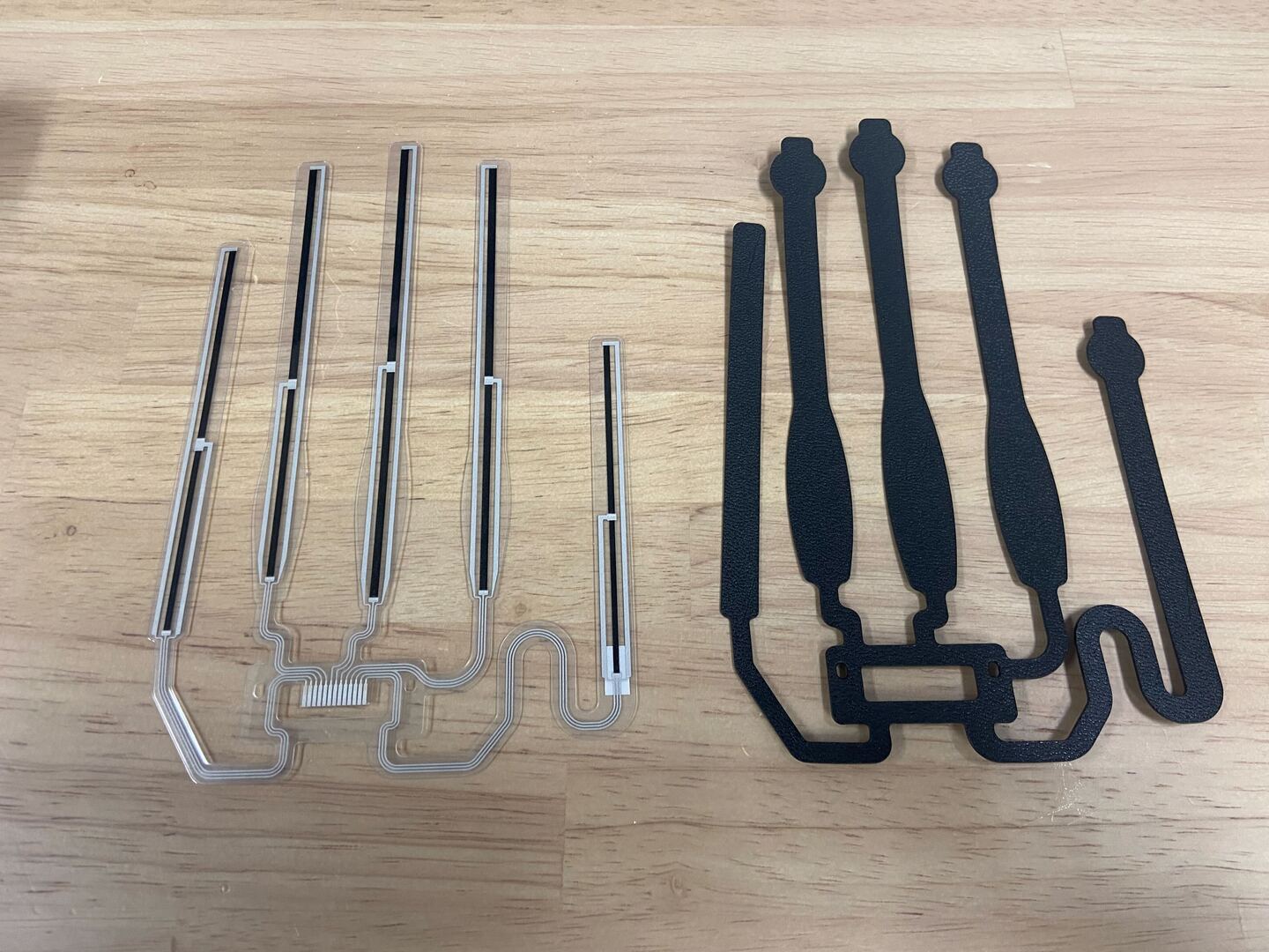
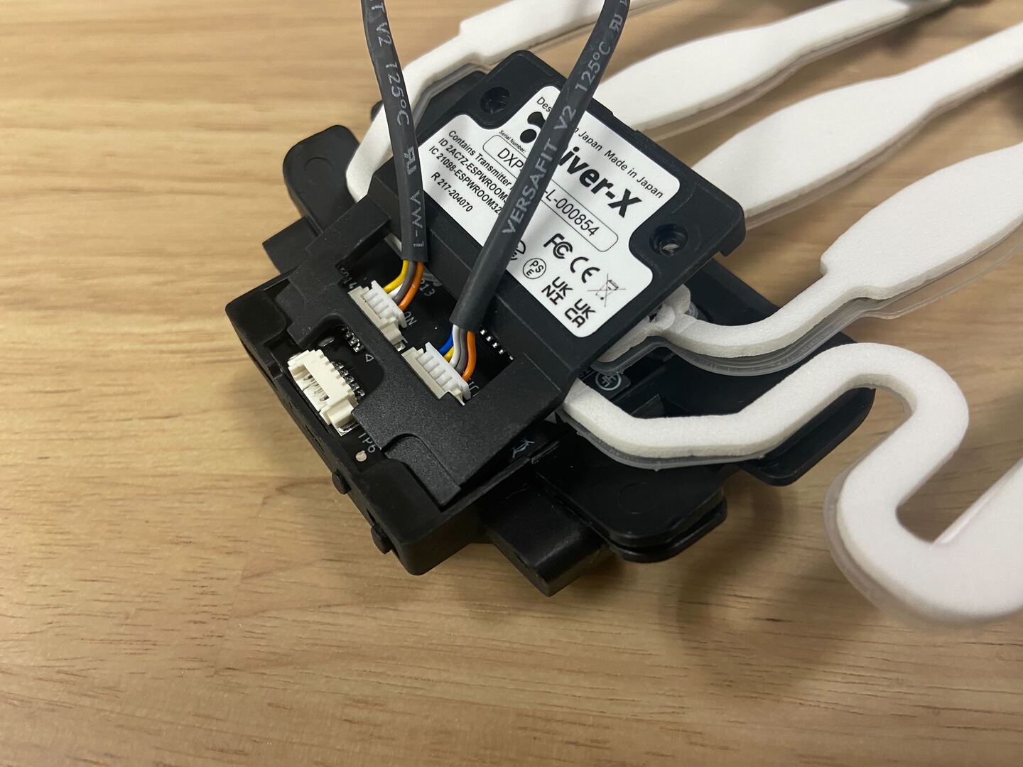
Separated state.
Peel off the black tape and separate the bending sensor from the black plate.
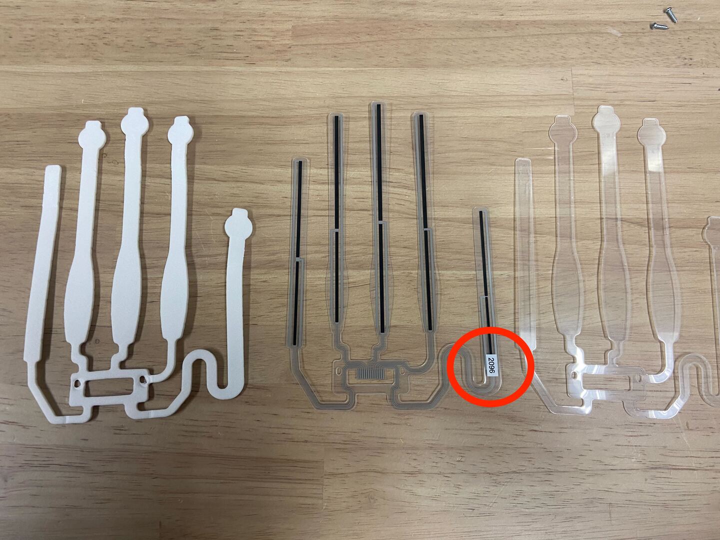
5. Attachment of New Impact Plate and Sponge
The bending sensor has a front and back. A sticker with the serial number is attached to the lower part of the sensor's thumb area. Place this side facing upwards on the table. In the future, work with the direction where the serial number sticker of the bending sensor is facing upward.
※ Although the images were for the left hand until now, they switch to the right hand images from here. I apologize for any confusion.
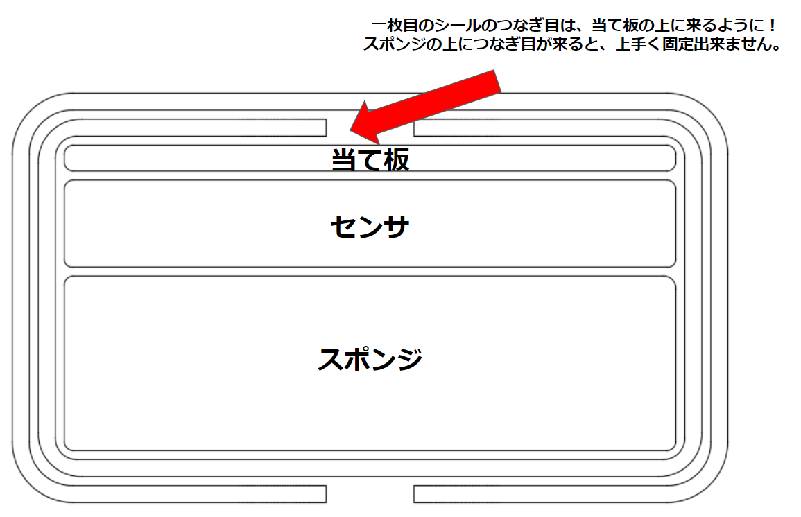
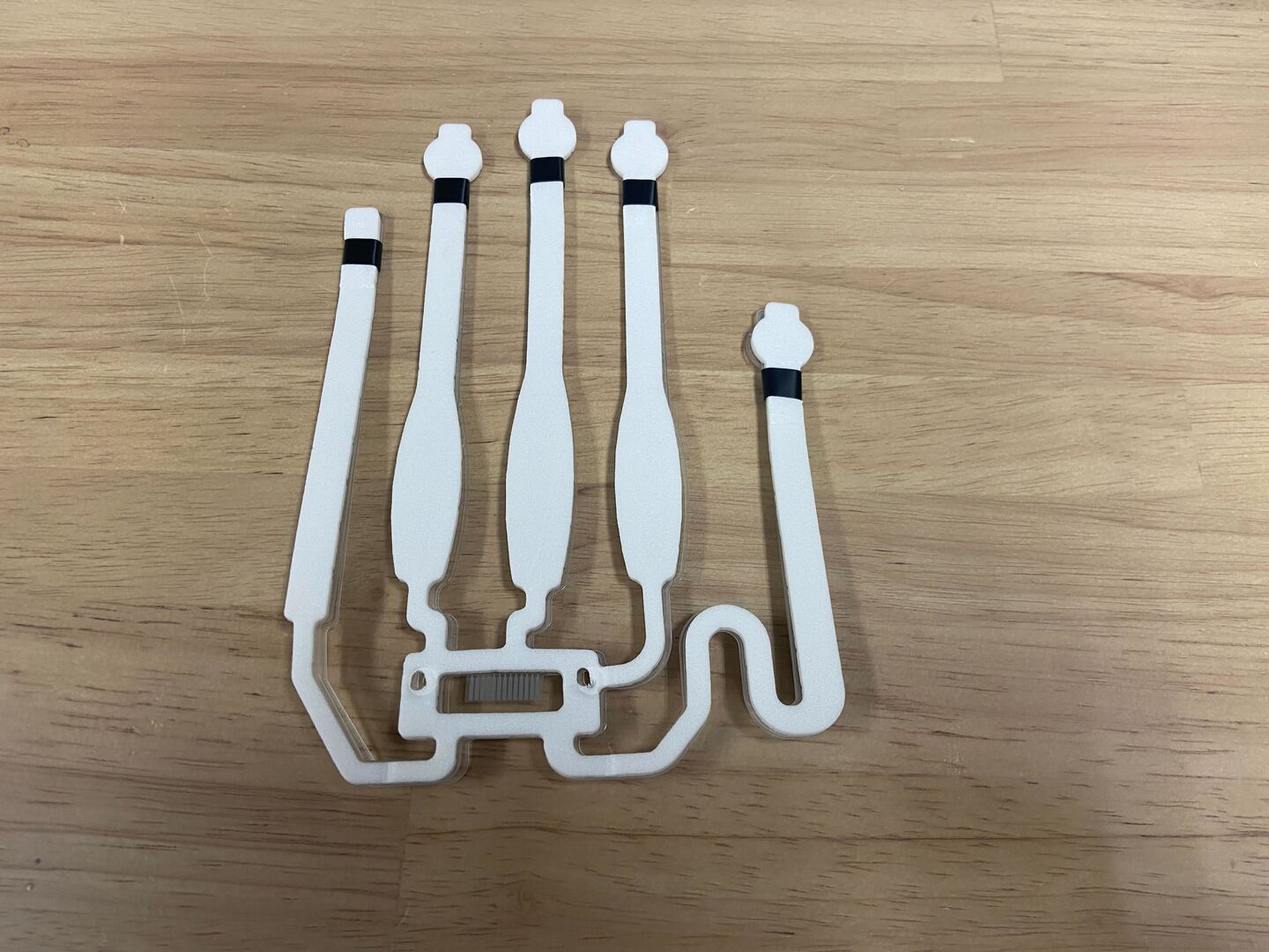
Stack the transparent plate, bending sensor, and sponge in that order from the bottom.
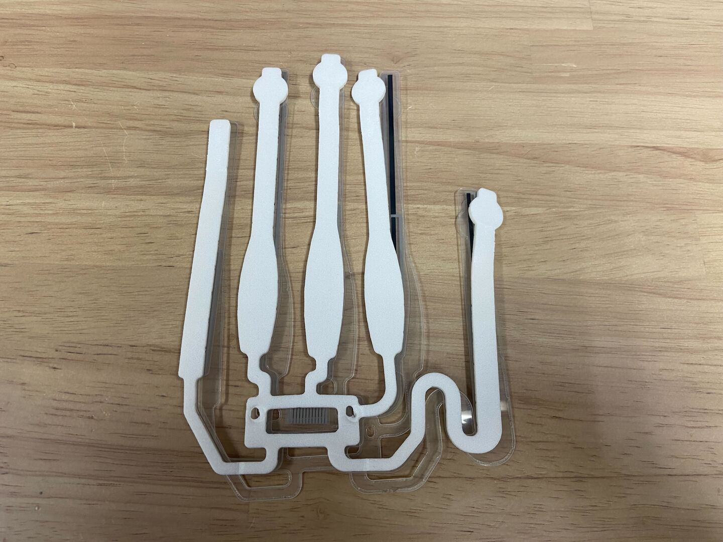
Secure the three sheets with the included stickers. Ensure that the ends of each sheet are aligned.
TIP
When applying the stickers, ensure that the seams are on top of the impact plate (film). If the seam is on top of the sponge, it may not adhere properly.
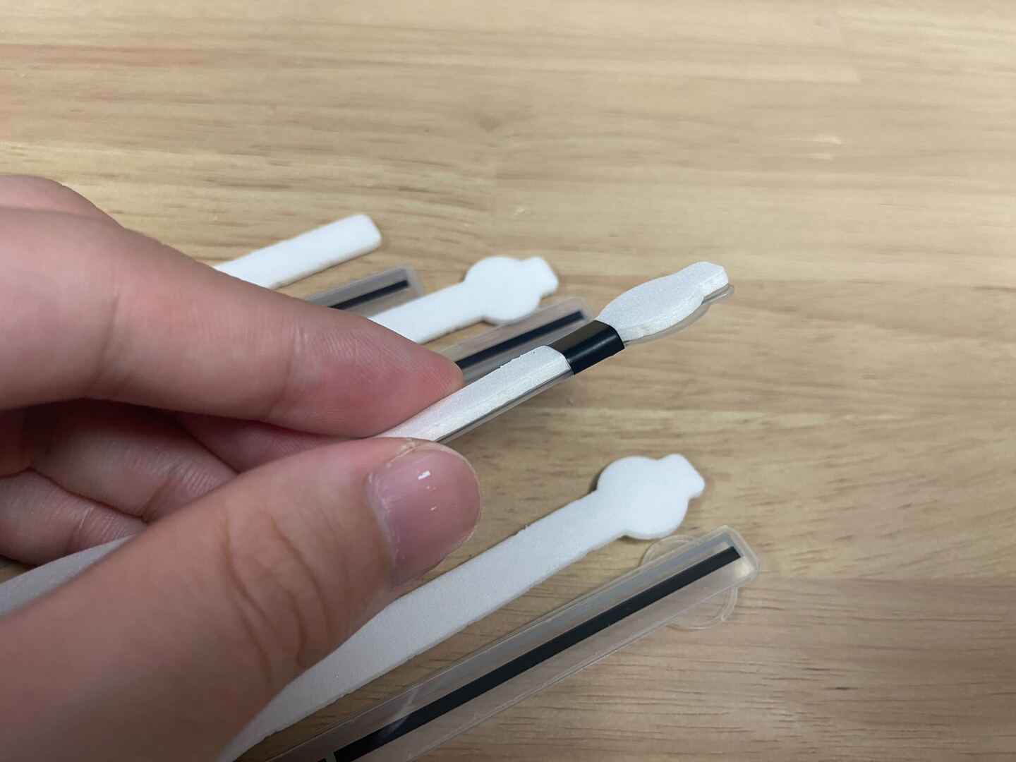
Also, for those with 30 stickers (short stickers), use two stickers to fix them to one finger, as shown in the image below. If you have 20 stickers (long stickers), fixing with one sticker is sufficient.
6. Connection of Main Body and Sensor
Unlock the thin yellow flap of the FPC connector and leave it lifted.
Insert the terminals of the bending sensor into the connector so that the white sponge is visible as shown in the image.
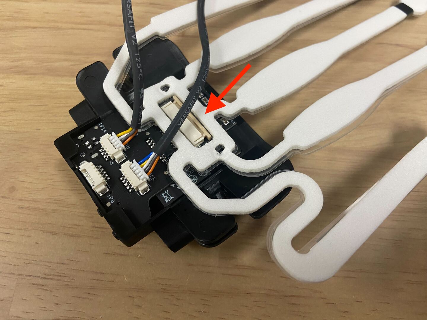
After completing the insertion as shown in the image, push down and lock the thin yellow flap of the FPC connector.
7. Attachment of Back Cover
Pass the cables through the holes in the back cover and bring the back cover back to its original position.
Insert the corners of the back cover into the corners of the main body.
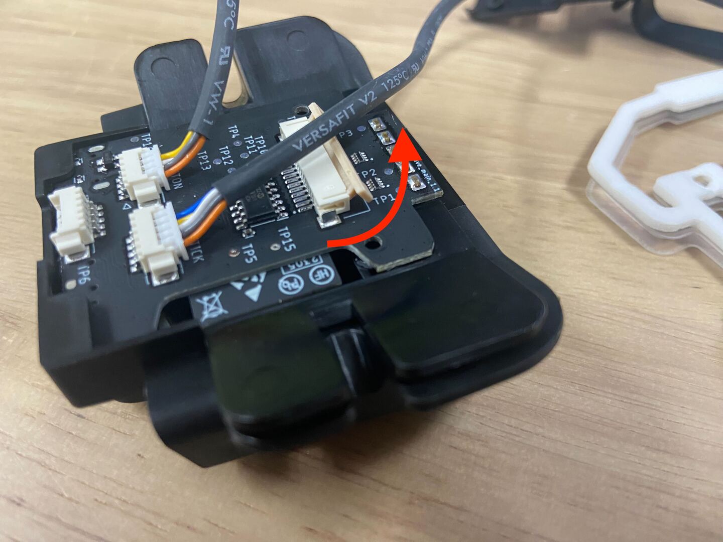
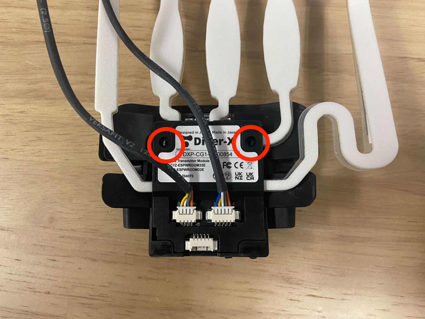
DANGER
Small electronic components are implemented in the red-circled area of the image. Pay close attention to avoid the back cover catching on this component.
When inserting the back cover, do so gently without applying too much force.
Align the holes in the back cover with the positions of the sponge, bending sensor, and insert the corners of the back cover into the corners of the main body.
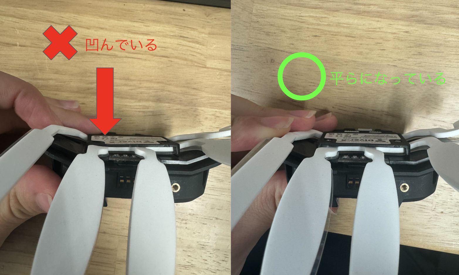
DANGER
After the heads of the screws are embedded in the back cover, do not tighten the screws further. Excessive tightening may apply pressure to the sensor, risking damage.
It's done.